
Guides

From a bag of parts to a saved battery. Each guide shows the video, then opens the documentation where it lives, on GitHub.

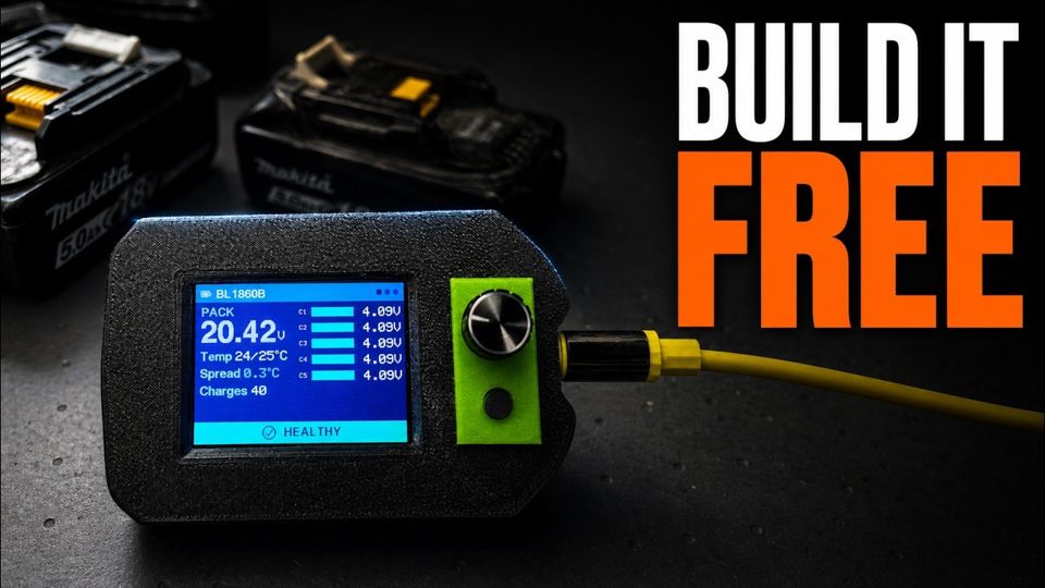
Your makita battery remembers everything you did to it! The full build, from 03:58.
  1. 03:58The parts list
  2. 05:48Ordering the PCB
  3. 07:11The tools you need
  4. 08:34Building it
  5. 12:37Wiring, inserts and final assembly
  6. 17:17First power up

Build a PocketOBI

The reference build: an ESP32-C3 SuperMini on the PocketOBI carrier board, a 2.4" screen with a rotary encoder, and a Makita LXT adapter.

You need: the carrier PCB (Gerbers are ready to upload), the parts on the BOM, an LXT adapter, a soldering iron and a USB-C cable.

The one trap: identify DATA and ENABLE by the ESP32 silkscreen, not by the adapter's connector numbering. B+ is never connected.

Next: Put the firmware on it

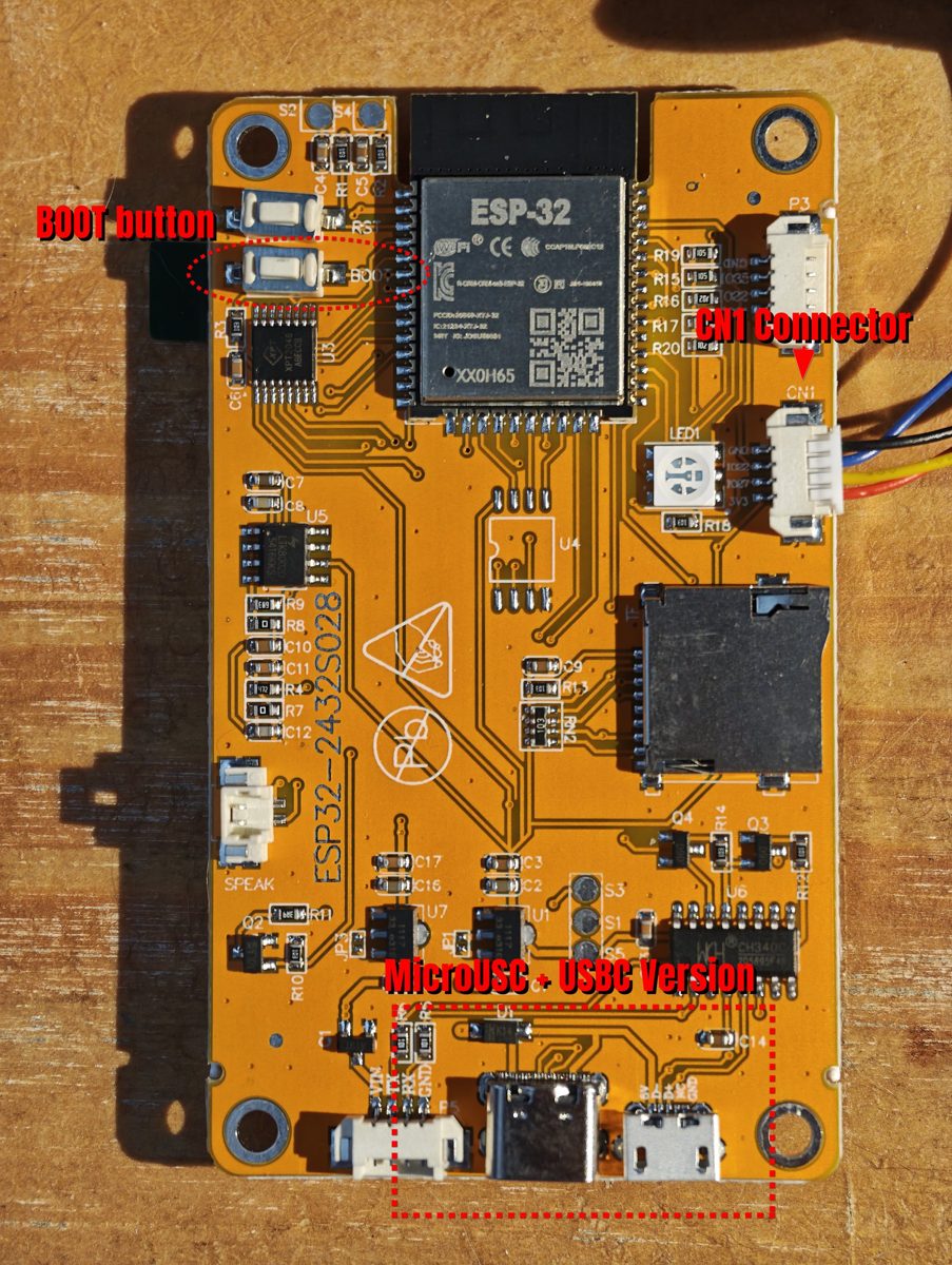
The CYD board (ESP32-2432S028R), with the BOOT button, the CN1 connector and the dual USB version marked
The dual-USB CYD. The whole pack connection fits on CN1.

Build it on a CYD instead

The "Cheap Yellow Display" runs the same firmware with a touch screen instead of the knob. Less soldering, but boards vary between batches. The ESP32-C3 build stays the reference.

You need: an ESP32-2432S028R (dual-USB, ST7789 revision), two 470 Ω resistors, an LXT adapter.

Next: Put the firmware on it

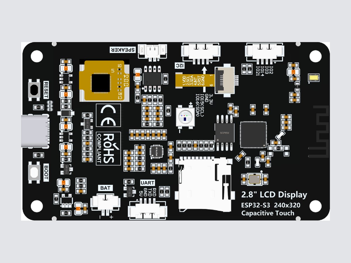
The ES3C28P board, back side, with the Expand, I2C, UART and BAT sockets labelled
The pack lead takes two sockets: Expand and I2C. Board render: LCDWiki.

Build it on an ES3C28P

Since PocketOBI 2.6, the firmware also runs on the ES3C28P, a 2.8" ESP32-S3 board with a capacitive touch screen. Same screens as the CYD, driven by touch. It also has a LiPo charger and a battery socket, but running it from a cell instead of USB is not tested yet.

You need: an ES3C28P, two 470 Ω resistors, two 1.25 mm socket leads and an LXT adapter.

The one trap: no single socket carries both the bus and 3.3 V, so DATA and ENABLE come from Expand, 3.3 V and ground from I2C. Leave the touch pins on I2C alone, and B+ is never connected.

Next: Put the firmware on it